

Circulators
Page Contents
Let us discuss the 3 Port Circulator S Matrix and 4 Port Circulator S Matrix using the (Scattering Matrix). We will also discuss the basics of 3 Port and 4-port Circulators and Difference between 3 port circulator and 4 port circulator
Definition of a Circulator:
In simple terms, Circulator is a device in which RF signal travels from one port to the next in one direction i.e. either clockwise or anticlockwise. There are 2 types of circulators based on the number of ports i.e. 3 Port circulators and 4 port circulators.
The microwave circulator is a multi-port device in which power is circulated from nth port to (n+1)th port only in One Direction. A 4 port circulator is most commonly used.
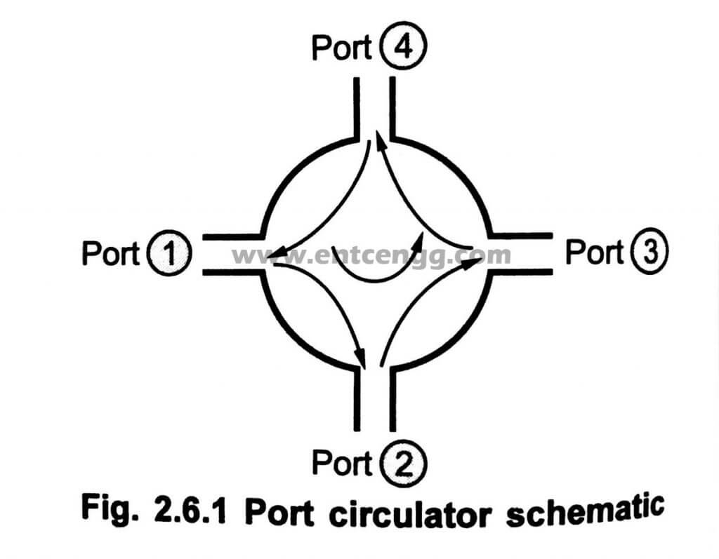
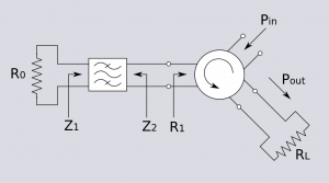
The following figure shows a 4 port circulator schematic.
The circulator is not a reciprocal component. All the 4 ports are matched and transmission of power takes place in a cyclic order only. An ideal circulator is perfectly lossless.
The circulator is a device in which microwave or radiofrequency signals entering any port are passed on to the next port in rotation only.
A port in this context is the point where an external waveguide or transmission line is connected to the device.
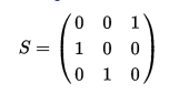
For a 3 port circulator suppose signal is applied to port 1 the output is observed at port 2 and port 3 remains completely isolated this is one of the main application of a circulator, if the signal is applied to port 2 then output is observed at port 3 and port 1 remains completely isolated so the scattering matrix of an ideal circulator is
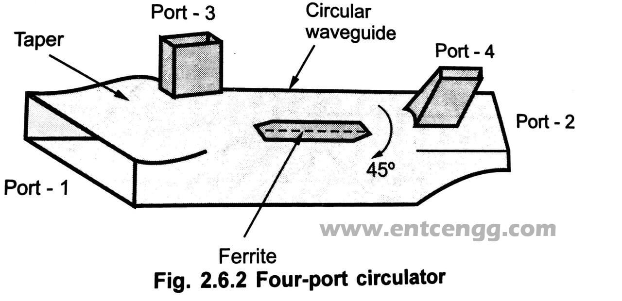
What is 4 Port Circulator?
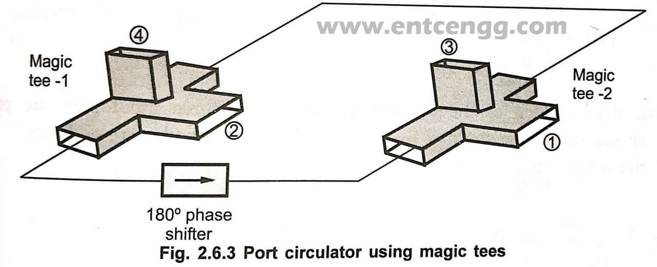
The 4 port circulator can be made using 2 magic T and one non-reciporcal 180 degrees phase shifter.
It can also be made using two 3-dB directional couplers with side holes and two non-reciprocal phase shifters.
Power entering port 1 travels along the magnetized ferrite. The direction of the E field vector gets rotated by 45°. Therefore power entered at port 1 appears at port 2. The power cannot be coupled to port 4 because ports 2 and port 4 are 90° out of phase. Similarly, Port 3 is coupled to port 4 and port 4 to port 1
4 Port Circulator using Magic Tees:
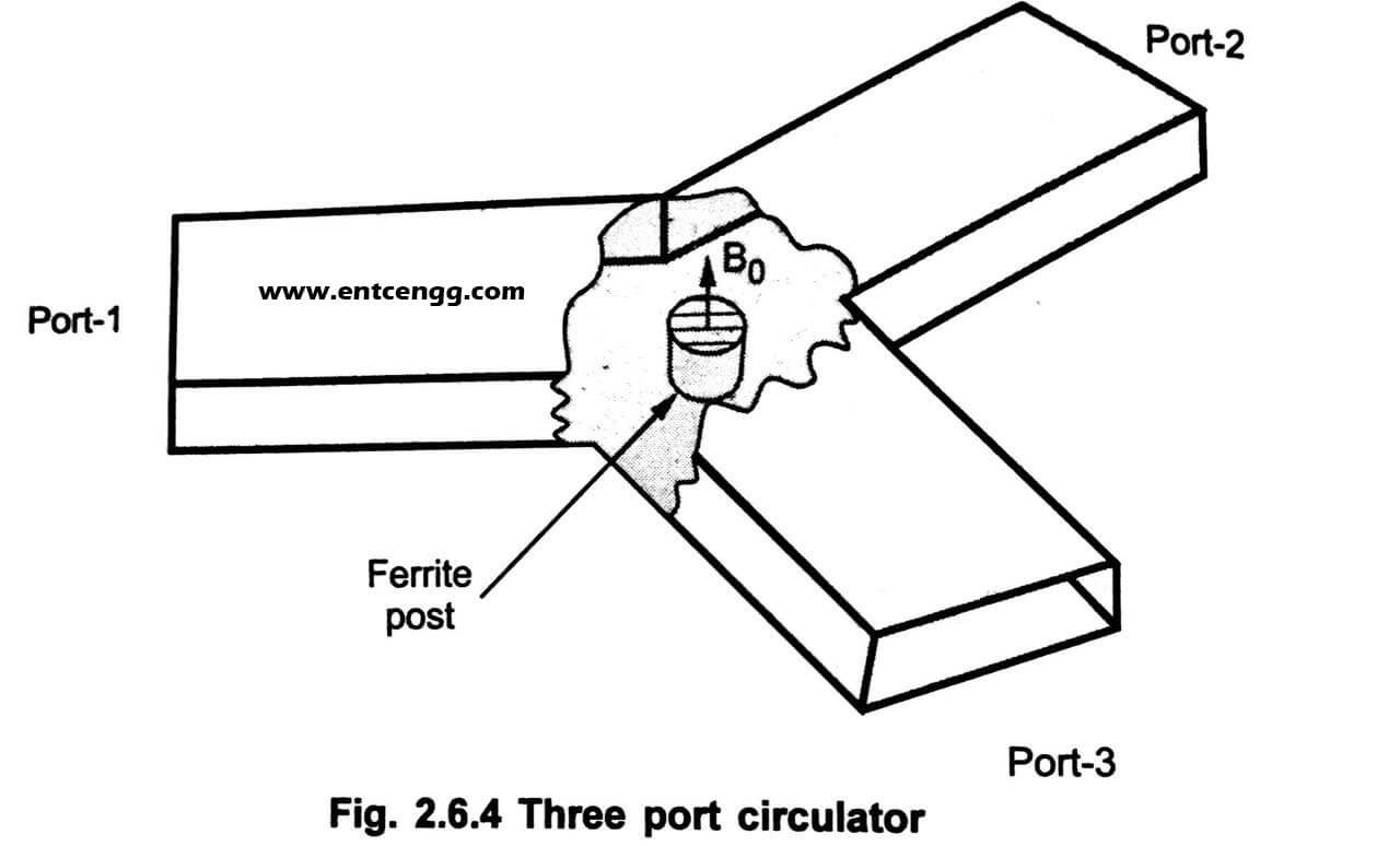
What is 3 Port Circulator?
The above diagram represents 3-port RF circulator. The signal that is to be transmitted travels from 1-port to 2-port and signal received at antenna travels from 2-port to 3-port as shown.
In simple terms, A 3 port circulator is formed by 120 degree H – Plane waveguide or by using stripline symmetrical Y junction.
A 3 port circulator is an asymmetrical Y-type junction of three identical waveguides with an axially magnetized ferrite post placed at the center. The ferrite post is magnetized by a static B field along the axis. It provides the necessary nonreciprocal property.
The junction can be matched by placing a suitable tuning element in each arm. It is an essential component used to isolate the input and output in a negative resistance amplifier. Three port circulators are also used to couple a transmitter to various receivers.
Difference between 3 Port Circulator and 4 Port Circulator
| 3 Port Circulator | 4 Port Circulator |
| 3 port circulator is formed by 120 degree H – Plane waveguide or by using stripline symmetrical Y junction | The 4 port circulator can be made using 2 magic T and one non-reciporcal 180 degrees phase shifter. |
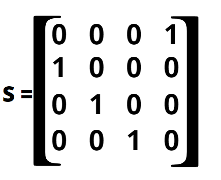
| S matrix is lossless, perfectly matched, non reciprocal of 3 port circulator is shown below | S matrix is lossless, perfectly matched, non reciprocal of 4 port circulator is shown below |
| [S] = | 0 0 S13| |S21 0 0 | |0 S32 0 | | [S] = |0 0 0 1 | |1 0 0 0 | |0 1 0 0 | |0 0 1 0 | |
Switchable circulators:
In these types of circulators electrical signals are applied to switch the orientation of the circulator from clockwise direction to counter-clockwise direction and vice versa.
The way the circulator is manufactured will stay in the default orientation in the absence of the electrical signal.
This technology is expensive but it makes its low loss and increases the power handling capacity
Also read Gyrator in Microwave Engineering
Bluetooth Architecture and Layers of Bluetooth
Circular Shifting – DFT Property Matlab Program
Principle of operation
Working with the Circulator is based on the principle of Faraday rotation. All the ports 1,2,3 and 4 are oriented such that the E field of transmitted signal couples to these ports successfully after going through Rotation of 45° in a clockwise direction.
Circulator Thumb rule:
The isolation of a circulator is equal to its return loss.
A circulator with the isolation of 25dB will have a return loss of 25 dB.
Let us think this way, if we terminate the third arm in a perfect 150 ohms along with the clockwise isolation we will measure in a counter-clockwise circulator will not be better than the stray signal that is bouncing off the perfectly loaded port because of reflected signal due to its mismatch to 150 ohms matched load.
Types of Circulators:
There are two types of circulators
Ferrite circulator and Non-Ferrite Circulator
Ferrite
Ferrite circulators are further classified into two types
- 4 port waveguide circulator which is based on Faraday rotation
- 3 port ‘Y’ Junction circulators
The second type is
Non-Ferrite
These are active circulators and hence require more power
The major drawback of transistor-based circulators is the power limitation and signal to noise degradation.
The solution for this is Varactors.
Characteristics of Circulators:
- Insertion loss < 1 dB
- Isolation approx =30-40 dB
- VSWR <1.5
Applications of circulators:
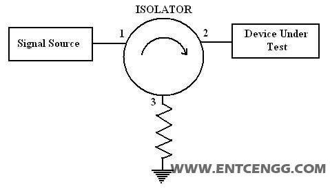
Isolator:
This is one of the most widely used applications of a circulator. The signal and power between the two ports remain completely isolated when the other port is terminated using a matched load.
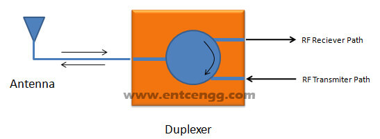
Duplexer:
The duplexer is used to merge two signals into one channel.
The circulator is used as a duplexer in radars to route the signals from the transmitter to the antenna and from the antenna to the receiver avoiding signals to directly pass from transmitter to receiver.
Reflex Amplifier:
It is a microwave amplifier circuit using negative differential resistance diodes like the tunnel diode or Gunn Diode. These diodes perform better at microwave frequencies than 2 port devices, but since the diode is a one-port device non-reciprocal component is required to separate the outgoing signal from the incoming signal.
Industry Applications:
- Drop-In Circulators
- Surface Mount Circulators
- SMA Coaxial Circulators
- N-Type Coaxial Circulators
- Drop-In & Connectorized Multi-Port Junctions (Contact Factory)
- Circulator pump
RF Circulators:
An Rf circulator is a 3 port device.
It is ferromagnetic in nature.
It is used to regulate signal flow within a circuit.
the working principle is similar to a circulator, signal to port 1 is transmitted to port 2 and remains isolated from port 3,
A signal from port 2 is transmitted to port 3 and remains isolated from port 1.
A signal to port 3 is transmitted to port 1 and remains isolated from port 1.
Circulators have minimal loss while transmitting signals.
Selection criteria for RF circulators:
Frequency(MHz):
It is the frequency at which the device operates with minimum loss and maximum output
Isolation(dB):
It is the measure of signals at the adjacent ports. i.e if the signal is applied between port 3 and port 1 then isolation is measured between port 3 and port 2
Power(W):
The level of power the device can handle while its operation.
Insertion loss(dB):
It is the signal loss of the input signal from one port to the next consecutive port.
It is the difference in the incident power at one port to the power received at another port.


")


very interesting post share.
Regards
classifications of non ferrite circulators ??