

Page Contents
Objectives:
- Builds the concepts of Pulse Analog communication Modulation.
- Understand the difference between angle modulation and use analog modulation.
- Figures out building a time division multiplexing signal.
- Introduces Sampling and hence reconstruction.
- Familiarizes the words such as Nyquist rate, Nyquist interval, and states the Nyquist Theorem.
- Construction of different types of Pulse Modulated signals.
- Presents Pulse Code Modulation technology and
- Links pulse analog communication and digital communication.
Forms of Pulse Modulation
- PAM, PWM ad PPM Analog Modulation schemes.
- A parameter of the pulse is varied in accordance
with a message signal
- PAM- Amplitude – Analog
Width – Discrete
- PWM – Width- Analog
Amplitude – discrete
- PPM – Position – Analog
Amplitude – Discrete
Steps For Analog To Digital Conversion
- Sampling Process
- Quantization
- Encoding
Pulse Modulation
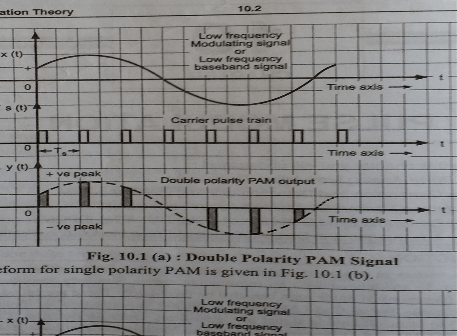
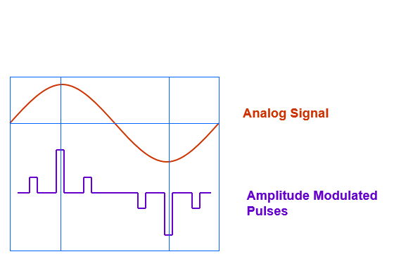
Pulse Amplitude Modulation (PAM):
* The signal is sampled at regular intervals such that each sample is proportional to the amplitude of the signal at that sampling instant. This technique is called “sampling”.
* For minimum distortion, the sampling rate should be more than twice the signal frequency.
ANALOG PULSE MODULATION (APM)
- In APM, the carrier signal is in the form of pulse waveform, and the modulated signal is where one of the characteristic (either amplitude, width or position) is changed according to the modulating/audio signal
- The three common techniques of APM are: Pulse Amplitude Modulation (PAM),
Pulse Width Modulation (PWM) and
Pulse Position Modulation (PPM).
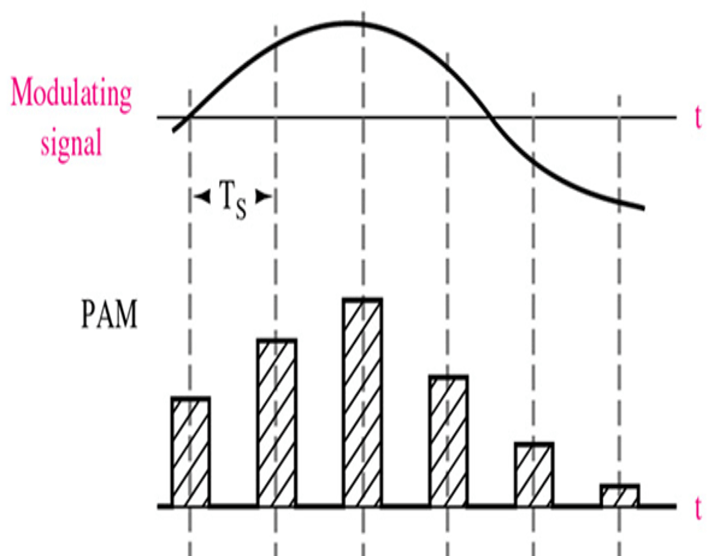
Pulse Amplitude Modulation (PAM)
- The simplest form of pulse modulation
- The amplitude of a constant width, constant position pulse (carrier signal) is varied according to the amplitude of the modulating signal.
- Basically, the modulating signal is sampled by the digital train of pulses and the process is based on the sampling theorem
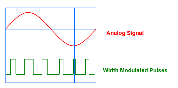
Pulse Width Modulation (PWM)
- The technique of varying the width of the constant amplitude pulse proportional to the amplitude of the modulation signal.
- Also known as Pulse Duration Modulation (FDM).
- Either the leading edge, trailing edge or both may be varied by the modulating signal.
Pulse Width Modulation (PWM)
- PWM gives a better signal to noise performance than PAM.
- PWM has an advantage, when compared with PPM, that is its pulse are of varying width and therefore of varying power content. PWM still works if synchronization between transmitter and receiver fails, whereas PPM does not.
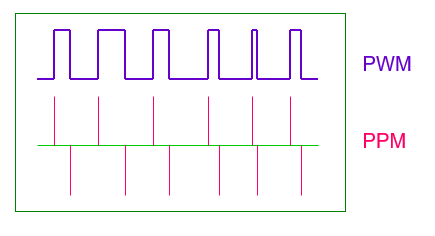
Pulse Position Modulation (PPM)
- PPM is when the position of a constant-width and constant-amplitude pulse within prescribed time slot is varied according to the amplitude of the modulating signal.
- PPM has the advantage of requiring constant transmitter power output, but the disadvantage of depending on transmitter-receiver synchronization.
- PPM has less noise due to amplitude changes, because the received pulses may be clipped at the receiver, thus removing amplitude changes caused by noise.
Waveforms Of PAM. PWM and PPM
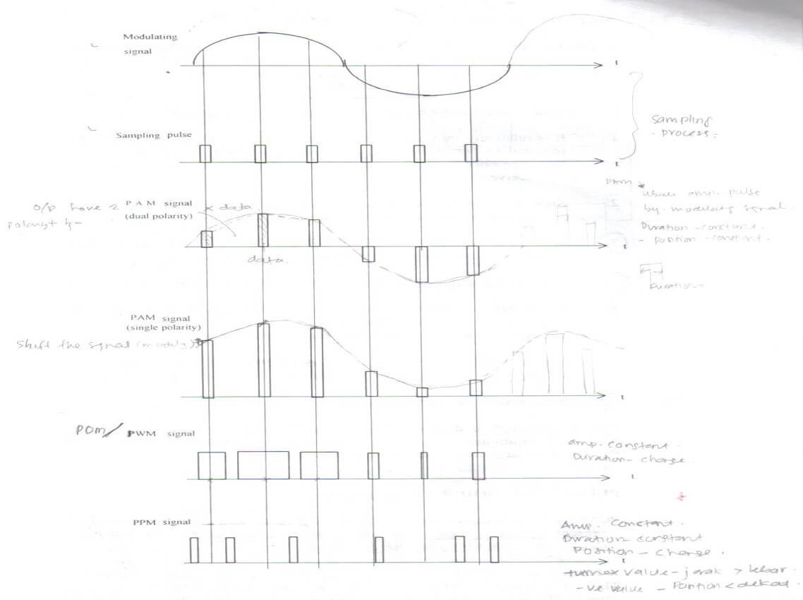
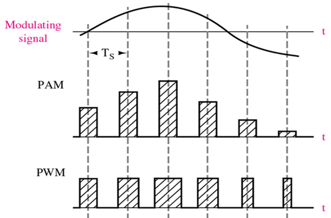
Pulse Width Modulation (PWM or PLM or PDM):
* In this type, the amplitude is maintained constant but the duration or length or width of each pulse is varied in accordance with the instantaneous value of the analog signal.
Pulse Position Modulation (PPM):
* In this type, the sampled waveform has fixed amplitude and width whereas the position of each pulse is varied as per the instantaneous value of the analog signal.
* PPM signal is further modification of a PWM signal. It has positive thin pulses (zero time or width) corresponding to the starting edge of a PWM pulse and negative thin pulses corresponding to the ending edge of a pulse.
* This wave can be further amended by eliminating the whole positive narrow pulses. The remaining pulse is called clipped PPM.
DIFFERENCE
PAM
The amplitude of the pulse is proportional to the amplitude of modulating the signal.
Band width of transmitting channel depends on the width of the pulse.
Instantaneous power of transmitter varies.
Noise interference is high.
Complex system.
Similar to A.M.
PPM
Relative position of pulse is proportional to amplitude of modulating signal.
The bandwidth of transmitting channel depends on the rise time of the pulse.
Instantaneous power remains constant. Noise interference is minimum.
Simple to implement.
Similar to P.M.
PWM
Width of pulse is proportional to amplitude of modulating signal.
The Bandwidth of transmitting channel depends on rise time of the pulse.
Instantaneous power of transmitter varies. Noise interference is minimum.
Simple to implement.
Similar to F.M.
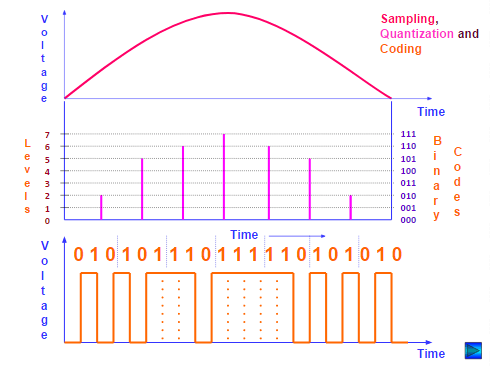
Pulse Code Modulation (PCM):
* Analog signal is converted into digital signal by using a digital code.
* Analog to digital converter employs two techniques:
- Sampling: The process of generating pulses of zero width and of amplitude equal to the instantaneous amplitude of the analog signal. The no. of pulses per second is called “sampling rate”.
- Quantization: The process of dividing the maximum value of the analog signal into a fixed no. of levels in order to convert the PAM into a Binary Code.
The levels obtained are called “quantization levels”.
* A digital signal is described by its ‘bit rate’ whereas analog signal is described by its ‘frequency range’.
* Bit rate = sampling rate x no. of bits/sample
Merits of Digital Communication:
- Digital signals are very easy to receive. The receiver has to just detect whether the pulse is low or high.
- AM-FM signals become corrupted over many short distances as compared to digital signals. In digital signals, the original signal can be reproduced accurately.
- The signals lose power as they travel, which is called attenuation. When AM and FM signals are amplified, the noise also get amplified. But the digital signals can be cleaned up to restore the quality and amplified by the regenerators.
- The noise may change the shape of the pulses but not the pattern of the pulses.
- AM and FM signals can be received by any one by suitable receiver. But digital signals can be coded so that only the person, who is intended for, can receive them.
- AM and FM transmitters are ‘real-time systems’. I.e. they can be received only at the time of transmission. But digital signals can be stored at the receiving end.
- The digital signals can be stored, or used to produce a display on a computer monitor or converted back into analog signal to drive a loudspeaker.
Reference Books for Analog Communication
Click Here to download Analog Communication PDFThis is one of the best books preferred for Analog Communication as it expalins each and every topic in detail and gives us a deep explanation and theorotical plus practical understanding of the subject analog communicaiton
Signals and Systems Reference TextBook
Baseband and Broadband signal Transmission
Electronic Devices and Circuits Reference TextBook


")


Interesting and useful content.Looking forward to upcoming posts. Keepup the good work.
Thank you so much for your kind words, your words are a motivation to me, I work for readers like you, Thank you
🙂