
What is Gyrator?
Page Contents
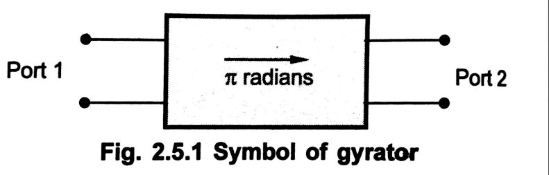
Gyrator is a nonreciprocal ferrite device. It is a two port device that has a relative phase shift of 180° in the forward direction and 0 (zero) phase shift in reverse direction.
The schematic symbol for gyrator is shown in the figure
When signal is transmitted from port 1 to port 2 it offers phase shift of 180° (π radians) and when signal if fed to port 2 it offers 0° phase shift to the signal
Hence it is also known as differential phase shift device.
gyrator symbol
Gyrator Construction:
Gyrator filter consists of a circular to rectangular waveguide transition both at dominant mode. A twin circular ferrite rod tapered at both ends is located inside the circular waveguide surrounded by permanent magnets which generate d.c. the magnetic field for the operation of ferrite.
A rectangular waveguide twisted by 90° is connected by input and reduces attenuation and also provide smooth attenuation of the polarized wave.
These were the gyrator analysis
Gyrator Working:
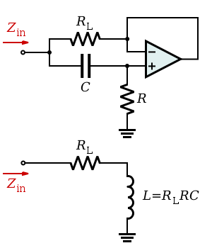
In the circuit below a gyrator, transformer is used to simulate an Inductor.
Inductors are very heavy and bulky to use so it is normally preferred to use some other components in place of them that are cheaper and lighter
The capacitor passes high frequencies causing the positive output of the op-amp to be closer to the input signal as the resistance is very large i.e. 20k very less current passes through the capacitor.
The op-amp keeps the negative input as the same level of positive, causing less current to flow through the capacitor because the voltage is nearly same as input, the circuit acts as an inductor blocking high frequencies
The capacitor blocks low frequencies, causing the positive input of the op-amp to be closer to ground.
The op-amp keeps the negative input at the same level as positive, causing more current to pass through the 1k resistor to ground, it passes low frequencies, just like an inductor.
Gyrator working
Gyrator and Transformer:
A gyrator is linear, lossless, passive and memory less two port device which is similar to an ideal transformer. However, a transformer couples the voltage on port 1 to the voltage on port 2 and current on port one to current on port 2, the gyrator cross couples the voltage to current and current to voltage.
2 gyrators cascaded together gives us a voltage to voltage coupling similar to an ideal transformer
Gyrator Applications:
A gyrator can be used to transform load into an inductance. at very low frequencies and low power, the behavior of the gyrator can be reproduced by small op-amp circuit.
It can be done by producing a small inductive element in a small electronic circuit. Before the transistor came into existence, coils of wire with large inductance might be used in electronic filters. An inductor can be replaced by smaller assembly containing a capacitor, op amp or transistor and resistor.
This is used in integrated circuit technology
gyrator as an inductor
The main application of gyrator is to reduce the size and cost of a system by removing the heavy, bulky, and expensive inductors.
For e.g. RLC bandpass filter characteristics can be realized with capacitors, op amps, and resistors without using inductors. Graphic equalization is possible using gyrators
There are two types of gyrators one is Passive gyrator and other is active gyrator.
A detailed video about gyrator
Also read


")


Very bad
Thanks for your response, We are striving hard to improve.