
Microstrip Patch Antenna Design Principles
Page Contents
Introduction
For consumer devices, wireless is everywhere! –
LTE 700 MHz,
GSM (850MHz/1.9GHz),
Wi-Fi (2.4 GHz),
Bluetooth (2.4 GHz),
GPS (1.575 GHz)
• Apple’s iPhone 4 is popular science for use of patch Antenna– But illustrates sizes and importance of good antenna design
Why microstrip patch antenna?
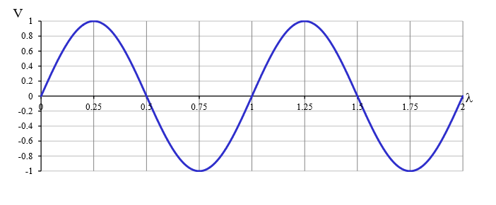
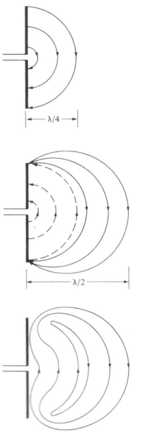
How is radiation achieved? • Wavelength is key: ?/2 ,
?ℎ??? ? = ?? /??(??)^1/2
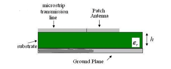
Microstrip Patch Antenna
With the microstrip antenna, l/2 is a bit too big for consumer mobile devices
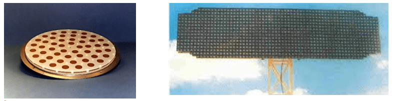
• Typically for space and military applications
• Easy to design/manufacture, yet very capable – Good value, great for antenna arrays
• Scale is better for millimeter wave RF (60+ GHz)
Design Methodology
• Find a “comfortable” model
– Transmission Line
– easiest, can be done in Excel
– Cavity
– higher accuracy, higher complexity
– Full Wave
– very accurate/adaptable, super complex
• Using specifications, generate initial design – Resonance frequency, gain, substrate, footprint, etc.
• Compare with an EM solver – Tune parameters such as ereff and DL (more details soon)
• Re-iterate design, prototype, measure
• Finalize design for manufacturing
For microstrip antennas, a good 1st step is to assume a standard substrate
– like Rogers RT/duroid 5880
• Importance of er, h
• To avoid cross polarization, keep 1 < W/L <1.5
• Rule of l/2 versus ~0.48l

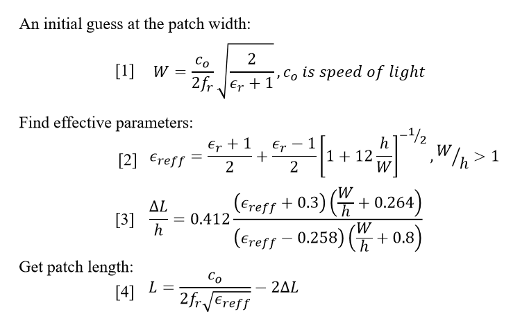
Footprint-Generating Equations
Also Check out other Microwave posts
End Fire Array Antenna Using CAD FEKO software
3 & 4 Port Circulator in Microwave
Gyrator in Microwave Engineering
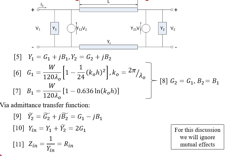
Circuit Equivalent Equations of patch antenna
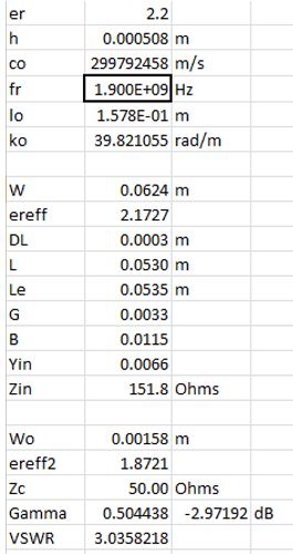
Quick Example patch antenna
• Rogers RT/duroid 5880 chosen:
– h=0.508mm, 100mm x 100mm board, er=2.2
• Want an antenna for GSM, fr=1.9GHz
• Use equations in Microsoft Excel
– W=6.24cm, L=5.30cm, Zin=151.8W
– Feed set to be 50W (standard): Wo=1.6mm
• Confirm antenna using an EM solver
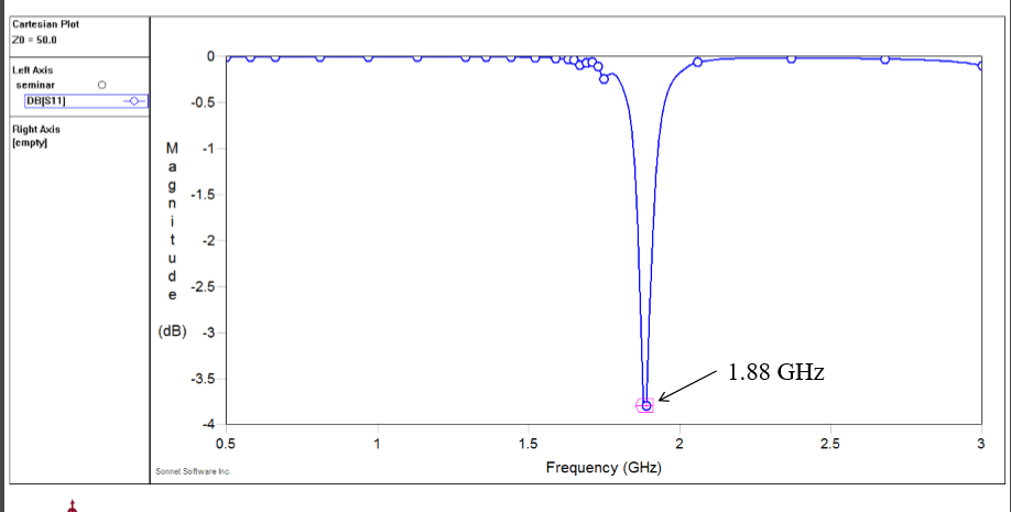
– Sonnet yields Zin=209.7W at 1.88GHz
Equations Implemented in Excel
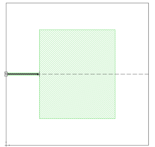
Sonnet Implementation
Sonnet S11 Response
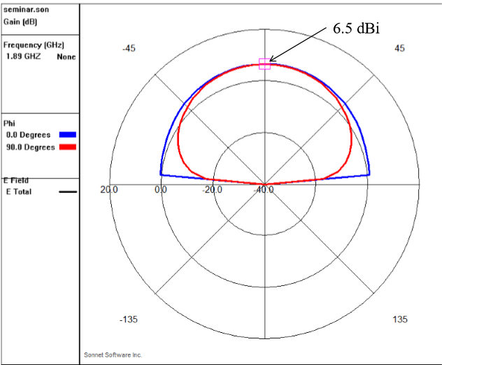
Sonnet Radiation Patterns
Future Efforts
• Gain full theoretical control of the patch antenna
– Change bandwidth, fr, E field/directivity at will
– Use a range of IMPATT locations and values
•Investigate adaptive array pattern control
– Optimize via array geometry
• OTA for PhD completion – Develop a test system, work with industry
• RF tx/rx chains plus control


")

