
Radiation Pattern, Return Loss, Impedance, Directivity, Gain and VSWR for ENDFIRE antenna
Page Contents

OBJECTIVE
To study various antenna parameters like radiation pattern, return loss, impedance, Directivity, Gain and beamwidth so as to get a thorough understanding of an End Fire Array antenna
THEORY :
In an array of identical elements, there are at least five controls that can be used to shape the overall pattern of the antenna. These are:
1.The geometrical configuration of the overall array (linear, circular, rectangular, spherical, etc.)
- The relative displacement between the elements
- The excitation amplitude of the individual elements
- The excitation phase of the individual elements
- The relative pattern of the individual elements
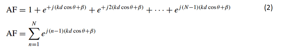
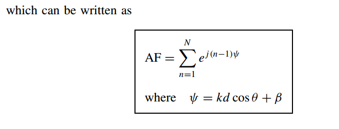
Pattern Multiplication :
E(total) = [E(single element at reference point)] × [array factor]
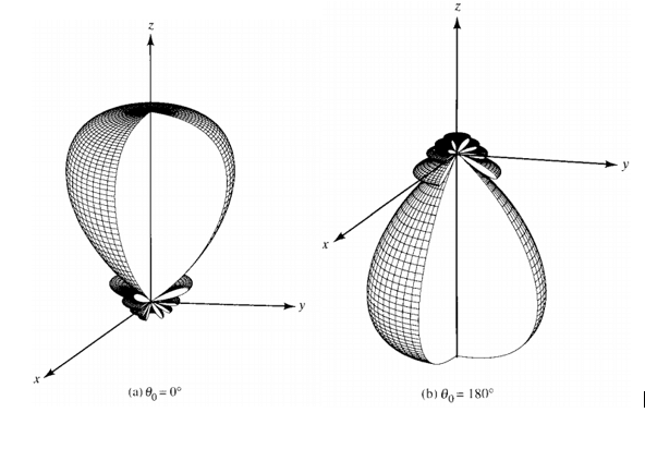
Instead of having the maximum radiation broadside to the axis of the array, it may be desirable to direct it along the axis of the array (end-fire).
As a matter of fact, it may be necessary that it radiates toward only one direction (either θ = 0° or 180° of Figure)
End Fire Array

Also read
3 & 4 Port Circulator in Microwave
Gyrator in Microwave Engineering
PROCEDURE :
- Set the model unit to Centimeters (cm).
- Create the variable for the frequency with a value of 600 MHz.
- Create the variable for lambda with value (c0/frequency)*100.
- Create a line with starting point coordinates at (0, lamda/4, lambda/4) and ending point coordinates at (0, -lamda/4, lamda/4).
- Create a line with starting point coordinates at (0, lamda/4, lambda/4+ lambda/4) and ending point coordinates at (0, -lamda/4, -lamda/4+ lambda/4).
- Create a line with starting point coordinates at (0, lamda/4, lambda/2+ lambda/4) and ending point coordinates at (0, -lamda/4, -lamda/2+ lambda/4).
- Create a line with starting point coordinates at (0, lamda/4, 3lambda/4+ lambda/4) and ending point coordinates at (0, -lamda/4, -3lamda/4+ lambda/4).
- Define frequency band as linear spaced discrete points starting from 500MHz to 600 MHz and take 201 points between them with 1 MHz step difference.
- Then assign the ports to the line at the middle.
- Connect port to a voltage source of 2V and assign phase equal to lamda/2.
- Create 3D far field.
- Create mess:
- Set the values for Global mesh sizes as suggested.
- Set the radius as 0.01.
- Click on show/hide mesh vertices to see the vertices.
- Then run FEKO to stimulate the antenna.
- Then go to POST FEKO.
For End Fire Array Radiation Pattern:
- Go to 3D.
- Then click on 3D far field.
For End Fire Array Gain Measurement:
- Go to the gain option.
- Then select Top left in the legend section to see the value for gain.
For End Fire Array Directivity measurement:
- Go to the Directivity option.
- Then select Top left in the legend section to see the value for directivity of antenna.
For End Fire Array Impedance Measurement:
- Click on icon add source data graph.
- Select frequency as 600MHz.
- Select quantity as impedance.
- On 2D graph we can see the impedance.
For End Fire Array Return Loss:
- Click on S11 in quantity section to measure return loss.
- Set the unit of both axis as dB.
- Select those frequencies which are below -10 dB by this we can measure the bandwidth.
- We can measure S11 from the graph.
For End Fire Array VSWR:
- Select quantity as VSWR.
- Select axis scale as linear.
- Select min value as 1 and maximum value as 2.
Set subdivisions as 6.


")

